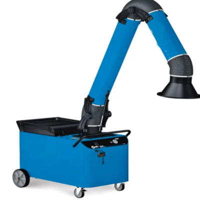
Fume Extractors
Ekaminingsolutions India Private Limited offers an extensive range of Fume Extraction System to protect men working in the manufacturing plants from hazardous gases and fumes. FES is installed to confine the fumes & unburnt particles of material, which are generated during melting and other industrial processes. Ekaminingsolutions offers technically advanced, highly efficient, custom made systems to suit specific industrial applications and satisfies the requirement of all the Pollution Control Boards across India and abroad. The system generally consists of suction hoods with articulated arm and also customized hoods required at. Centrifugal ID fan is also provided as a part of the Fume Extraction System (FES).
How Does It Work
Ekaminingsolutions fume extraction systems consist of three basic parts: a capture point where fumes are captured, an airflow source to pull fumes through the system, and a filter system to remove the pollutants.
FUME CAPTURE
The most efficient fume extraction systems remove the fumes as close as possible to their source. The best way to accomplish this is always dictated by the type of work being done: For tasks involving a small work area, such as hand soldering, the collection point can be situated extremely close to the source of the fumes, almost at the tip of the soldering iron. This is called Tip Extraction. For tasks that involve a larger working area, a higher volume fume extraction method must be used, consisting of hood or nozzle situated over the source of the fumes. This is called Volume Extraction.
AIRFLOW SOURCE
The airflow source for Ekaminingsolutions fume extractors are centrifugal blowers. These blowers provide the required vacuum and airflow to draw the unhealthy fumes through the filtration system and exhaust the clean air.
FILTER SYSTEM
Depending on the type of application, our fume extraction system uses specially designed cartridge filter(s). These filters intake the fume and post filtration exhaust clean air.
Specification
|
Model
|
Power
|
Dimensions
LxWxH(mm) |
Airflow
(m3/hr) |
Static Pressure
(mm of H2O) |
Weight
(Kg) |
Arm Configurations | ||
| Diameter (mm) |
Length (m) | Qty | ||||||
| SMOVEX 1.0 |
1 Hp |
1000 x 750 x 1250 |
1400 | 100 | 110 | Ø100 | 2 | 1 No |
|
SMOVEX
2.0 |
2
Hp |
1000
x 750 x 1250 |
1850
|
100
|
150
|
Ø100 | 2 | 2 No |
| Ø160 | 2 | 1 No |
||||||
|
SMOVEX
3.0 |
3
Hp |
1100
x 750 x 1300 |
1950
|
150
|
160
|
Ø100 | 2 | 2 No |
| Ø160 | 2 | 1 No |
||||||
|
SMOVEX
5.0 |
5
Hp |
1100
x 750 x 1300 |
2850
|
250
|
180
|
Ø100 | 2 | 2 No |
| Ø160 | 2 | 2 No |
||||||
